Materials and Metal Forming
Metal forming
The Metal Forming Lab, located in Rougeou Hall room 139, is operated by William J. Emblom, Ph.D., P.E. Dr. Emblom’s research focuses on forming and processes metals – particularly sheet and tube forming. His research philosophy is that all theoretical work must be verified by experimental results and all experimental data must be evaluated based upon theoretical analysis.
Stamp Forming
The automotive industry has been pursuing the using of light weight metals such as aluminum and magnesium as well as high strength steels in order to reduce weight. However, these materials are more difficult to form than conventional steels. Dr. Emblom has been pursuing the use of closed-loop control during stamp forming processes in order increase the formability. In Dr. Emblom’s work he has incorporated embedded force and wrinkle sensors in order to monitor stamp forming processes and active tooling elements in custom built dies that can be adjusted during stamp forming. He is pursuing closed-loop control systems for this stamp forming die and had demonstrated that implementing closed-loop control during the stamp forming process results in reduced wrinkling and increased draw depth without tearing.
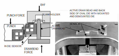
Figure 1 - Tooling for closed-loop control die. the lower die with sensors mounted and demounted. Active draw beads are also seen.
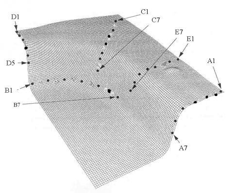
Figure 2 - FEA model for studying closed-loop control for stamp forming
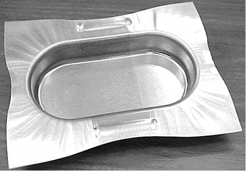
Figure 3 - Aluminum Oval panel with strain grids. This panel was used to study implementing closed-loop control of the stamp forming process.
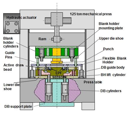
Figure 4 - 125-ton Research Press
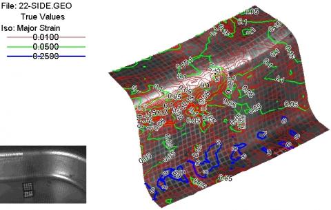
Figure 5 - Strain map from tests using the 125-ton press and oval die. Strains were measured using the ASAME strain measurement system. This test utilized draw bead height in closed loop-control of local forces for the oval pan.
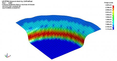
Figure 6 - Non-linear FEA (LS-DYNA) analysis of a cup forming experiment. This model is a quarter model of an entire cup. The model is being used to develop strain-based control of stamp forming.
Microscale Sheet and Tube Hydroforming
An new custom built multiscale sheet hydroforming press capable of 60,000 psi of pressure (415 MPa) and 60 tons (530 KN) of clamping force are used to form parts as small as 0.04 inches (1 mm) in diameter. Dr. Emblom is using this new press to develop new methods for producing fuel cells, microscale heat exchangers, biomedical devices, and MEMS. His work has resulted in a new method for measuring strains, studies on the effect of roughness at the microscale, and changes in the grain structure of sheet metal at the microscale. In addition, Dr. Emblom has a new microscale tube hydroforming press. This press can form complex parts out of stainless steel tubes as small as 0.04 inches (1 mm). Currently he is investigating material characterization and methods for improving material properties during forming. This work is aimed fuel cell research and the development of microfluidic devices.
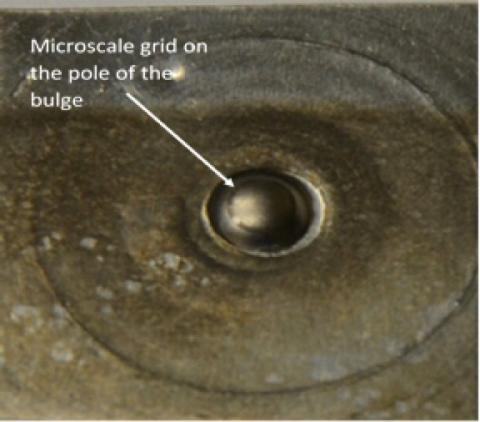
Figure 7 - A 5 mm diameter hydrostatic bulge test result with microscale grid for measuring strain.
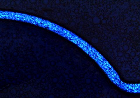
Figure 8 - Microscopic photo of half of a hydroformed part that was used for studying material properties of sheet metal. This part is about 2 mm (0.08 inches) high.
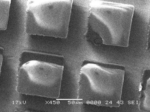
Figure 9 - 127 μm (center-to-center) lithographed grids on stainless steel work pieces. These are used to produce electrochemically etched grids on the stainless steel.
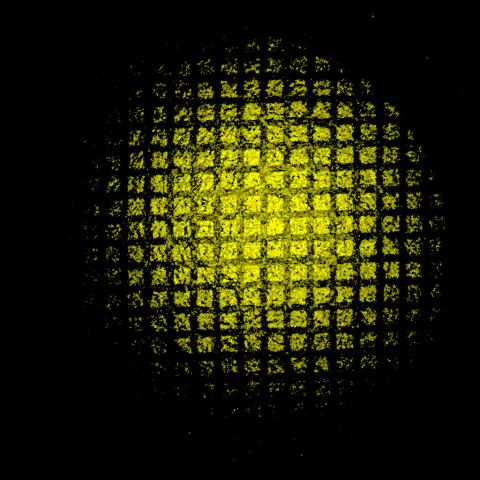
Figure 10 - Microstrain image of a hydroformed part. The deformed grids are used to determine material properties in a process developed at UL Lafayette.
Friction Stir Welding
Friction stir welding is becoming a very popular method for both processing material in order to obtain ultrafine grain material and to join metals, even dissimilar metals. Dr. Emblom has been working on friction stir welding of materials such as low carbon steels, aluminum, and magnesium.
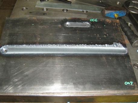
Figure 11 - Examples of friction stir welding in a mild steel plate.
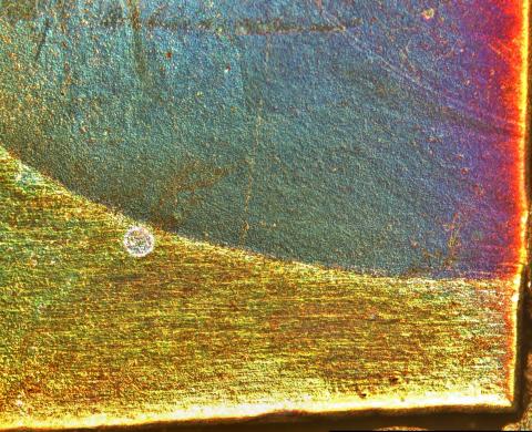
Figure 12 - A micrograph of aluminum after friction stir welding. The upper portion shows the ultrafine grain structure of the stir zone where the welding tool stirred the material. The lower section is the base material and shows the courser grain structure. There is a very thin region in between these two regions where the aluminum was heated enough to recrystallize.